Vacuum Tube Tesla Coil
Vacuum Tube
In electronics, a vacuum tube, an electron tube, or valve (British usage) or, colloquially, a tube (North America), is a device that controls electric current flow in a high vacuum between electrodes to which an electric potential difference has been applied.
The type known as a thermionic tube or thermionic valve uses the phenomenon of thermionic emission of electrons from a heated cathode and is used for a number of fundamental electronic functions such as signal amplification and current rectification.
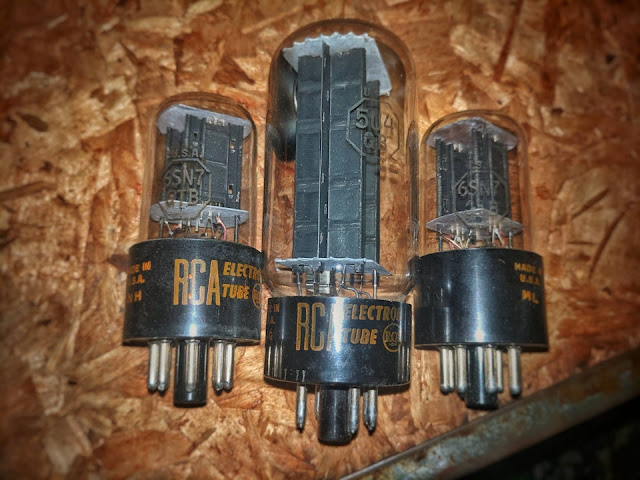
Vacuum Tube 6sn7 and a 5u4gb
In the early 21st century, many of us have never even heard of vacuum tubes, and the few who have only know that they were used in old electronics. Therefore, before I begin this project, I feel the need to explain how they work.
Picture 1:
Picture 2:
Picture 3:
Picture 4:
Lets take a look at picture 1. This is the standard symbol for a vacuum tube diode. A diode only conducts electricity in one direction. They can be used to turn an alternating current into a direct current. In the diagram, the bottom half hexagon is the filament. It is just like the filament inside of an incandescent lightbulb. The line above it is called the plate. The circle around the filament and plate represents the (usually glass, sometimes metal) envelope of the tube. Almost all of the air inside of this envelope has been evacuated, there is a vacuum. This will become important later.
Now, lets take a look at picture 2. Here we have applied a voltage between the filament and the plate. The filament is negatively charged, and the plate is positively charged. While the electrons in the filament are attracted to the plate, there is not enough voltage for them to do so on their own. So how can we get them to jump? Take a look at picture 3.
In picture 3, a few new things have appeared.First, we have a 10 volt power supply connected to each side of the filament. Just as in an incandescent lightbulb, this heats the filament up. The negative side of the power supply is still connected to the filament, but the positive side is not. Notice that now, the negatively charged electrons are stil flowing into the filament from the 100 volt power supply, but something is different. Why are they floating around the filament? As the filament heats up, thermionic emissions occur. Essentially, the electrons are shaken off of the filament by its thermal energy. This can happen because there is a vacuum. So now, the question is: What happens when we connect the positive side of the 100 volt power supply to the plate? Take a look at picture 4 to find out.
In picture 4, the positive side of the 100 volt power supply is connected to the plate. We have zoomed back towards the tube. In the picture, the electrons floating around the filament are moving towards the plate! There are no air particles to hinder their passage, so after the thermionic emission occurs, the positively charged plate attracts them, and they accelerate towards it, hit it, and move along the wire back into the power supply. That's how a vacuum tube diode works.
The principle of operation is relatively simple, but a Tesla Coil such as the one that we are building is an oscillator. That means that there is a feedback system that turns the diode on and off, to accomplish this, we use a triode.
Triode
Vacuum Tube - UX245
The first true electronic amplifier was the vacuum tube triode. It works because like charges (in this case, electrons) repel each other. Take a look at picture 1. It looks similar to the symbol for a vacuum tube diode, but it has an extra part that looks like a grid between the plate and filament.
This grid normally allows electrons to pass through itself for diode operation, but as it grows more and more negatively charged, it allows less and less electrons to travel from the filament to the plate due to electrostatic repulsion. In this way, you can regulate the flow of a relatively large current by using a relatively small one.
Tesla Coil
Tesla coils produce dramatic high-frequency, high-voltage electric sparks. They utilize the principles of transformers, ac driven circuits, and RLC transients.
Photo - Tesla coil. The 60 Hz power source on the left drives an LC circuit that, when the voltage is high enough, causes sparking across the spark gap. This drives the primary on the right into oscillation at its high resonance frequency (on the order of a MHz). The Tesla coil, coupled weakly to this oscillation, draws off energy, at a high voltage and at the frequency of the resonance.
A Tesla coil circuit uses two transformers. The first consists of a step-up iron core transformer at 120 V and 60 Hz, which drives the secondary to 25 KV and 60 Hz. This charges up a low C capacitor and a spark gap (which, when it is not sparking, may be thought of as a capacitor), in series with an inductorL. Including the resistance in the wires, this is an RLC circuit. Because 60 Hz is a relatively low frequency, the voltage associated with the inductor L is not very high, so the voltages across the capacitor and the spark gap are both nearly 25 KV. A glass sheath keeps the capacitor from sparking when subjected to such high voltage, but nothing prevents the spark gap from sparking. When that occurs, charge rushes across the spark gap, thus taking this RLC circuit out of equilibrium. It then undergoes transients, which consist of a damped RLC resonance at a frequency on the order of a MHz. In contrast to what happens for the low-frequency 60Hz voltage from the power transformer, for the high-frequency voltage associated with the LC circuit, the inductor couples to the step-up air transformer. This raises the high-frequency voltage of the latter to on the order of a MV. The many-turn secondary coil of this second transformer, which can be thought of as a parasite off the main RLC circuit, is what is meant by the Tesla coil.
The Vacuum Tube Oscillator
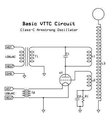
A Tesla Coil is essentially a very large oscillator. When the primary side of the coil oscillates at the natural frequency of the secondary side, resonance is achieved. This is a fundamental concept that is used in all Tesla Coils and other resonant transformers (such as the ones found in many switch-mode power supplies, and CRT television sets). The Vacuum Tube Tesla Coil that I detail here uses a configuration known as an Armstrong Oscillator.
In the standard model of a transformer, there are two coils, a primary and a secondary coil. Currents are usually induced from the primary coil to the secondary coil (although the opposite sometimes happens, usually with destructive results), this is a concept that we will not go over now, if you are unfamiliar with it, then this is a good place to become acquainted: http://en.wikipedia.org/wiki/Transformer. However, an Armstrong Oscillator works by introducing a third coil, called the feedback, or sometimes "tickler" coil.
Currents are not only induced from the primary coil into the secondary coil, but also into the feedback coil. This feedback is then used to turn off the oscillator by blocking current from flowing into the primary coil. However, when the primary coil is turned off, current is no longer induced into the feedback coil, and it no longer blocks current from flowing through the primary coil. In this way, the cycle repeats indefinitely, until it is interrupted, or the power is switched off.
Vacuum Tube Tesla Coil
Here is the particular schematic for the Tesla Coil that we will be building:
A few things that you should note are that I have found that you should make the primary coil (L1) slightly larger but allow for it to be tapped every other turn. Also, I've noticed that a slightly larger (~2nF) tank capacitor (C1) works better for my coil, but this could vary. Also, if you are adventurous enough, you might consider using a level shifter to double the voltage to the 811A tubes to 4000VAC RMS and then use a staccato circuit (something you should consider even without the level shifter) to keep the tubes running cool. However, since this is a slightly more advanced project I will not cover it here (yet!)
Tesla's Radiant Energy - Cold Electricity from Tesla Coils - Vacuum Tube Tesla Coil:
By replacing the Spark Gap in the Tesla Coil Circuit with a Vacuum Tube, we still generate Cold Electricity!
Special for you! How to build a homemade generator - radiant energy
Maybe you like:
A Practical Guide to Free-Energy Devices: Motionless Pulsed Systems
✰* Revealed At Last: Ancient Invention Generates Energy-On-Demand
✔ Nikola Tesla’s method of magnifying electric power by neutralizing the magnetic counter-forces in an electric generator
✔ Currents are 180 out of phase with each other, Lenz's law naturally is broken
✔ Principle of Resonance to achieve Overunity
A Practical Guide to Free-Energy Devices: Motionless Pulsed Systems
✰* Revealed At Last: Ancient Invention Generates Energy-On-Demand
✔ Nikola Tesla’s method of magnifying electric power by neutralizing the magnetic counter-forces in an electric generator
Generates Energy-On-Demand: Easy Power Plan Will Change Our World Forever
✔ Currents are 180 out of phase with each other, Lenz's law naturally is broken
✔ Principle of Resonance to achieve Overunity
Vacuum Tube Tesla Coil
 Reviewed by Re-programming Life
on
4:12 AM
Rating:
 Reviewed by Re-programming Life
on
4:12 AM
Rating:


No comments: